

According to industry research by the Construction Industry Institute, rework can account for 5–15% of total construction costs, with a significant portion attributed to design coordination issues, incomplete documentation, and communication gaps. Similarly, studies by Autodesk indicate that poor project data and miscommunication contribute substantially to costly rework and schedule delays across the construction industry.
Shop drawings play a critical role in bridging the gap between design intent and construction execution. They provide the detailed dimensions, fabrication requirements, material specifications, and installation information that contractors, fabricators, and field teams rely on to build accurately. However, the quality and usability of shop drawings depend heavily on the Level of Development (LOD) of the underlying BIM model.
Understanding the difference between LOD 300, LOD 350, and LOD 400 helps project teams define expectations, reduce rework, and ensure that BIM deliverables align with each phase of the project. This blog explains each LOD level, when it should be used throughout the project lifecycle.
What Does LOD Mean?
LOD (Level of Development) defines how much geometric detail and non-graphical information a BIM element contains at a specific stage of a project.
It answers questions such as:
- How accurate is this model?
- Can it be used for coordination?
- Is it suitable for fabrication?
- Can it be installed directly from the model?
Higher LOD doesn’t always mean “better.” It simply means the model contains the information required for a particular project stage.
LOD 300 – Design Development
What is LOD 300?
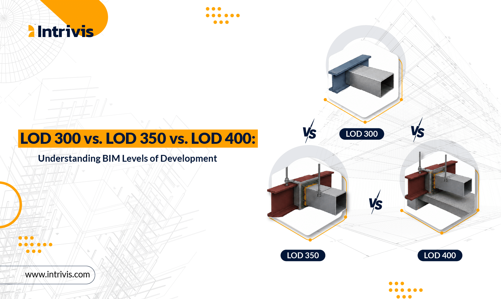
LOD 300 represents a model where building components are accurately modeled with correct size, shape, quantity, orientation, and location. At this stage, elements represent the intended design but are not yet fabrication-ready.
Typical Elements
| Architectural | Structural | MEP |
|
|
|
Deliverables
- Construction Documents
- Permit Drawings
- Quantity Take-Offs
- Design Validation
- Client Review Models
Best Used For
- Design Development
- Owner Approval
- Cost Estimation
- Construction Documentation
LOD 350 – Coordination Model
LOD 350 builds upon LOD 300 by introducing connections and interfaces between systems. Rather than modeling individual components alone, it illustrates how disciplines interact. This is where BIM begins to unlock its real value.
Additional Information Included
Besides geometry, LOD 350 models include:
- Supports
- Hangers
- Sleeves
- Openings
- Penetrations
- Equipment clearances
- Connection interfaces
Why LOD 350 Matters
LOD 350 goes beyond representing individual building components by defining how different systems interact with one another. For example, where an HVAC duct passes through a structural beam, LOD 300 models only the beam and duct, whereas LOD 350 includes critical coordination details such as openings, clearances, sleeves, and connection interfaces. This additional level of detail enables project teams to identify and resolve clashes during the coordination phase, minimizing costly rework, construction delays, and field modifications.
Typical Uses
- Clash Detection
- Coordination Meetings
- BIM Coordination
- Multi-discipline Reviews
- Construction Planning
LOD 400 – Fabrication Model
LOD 400 contains fabrication-level information. Models are detailed enough that manufacturers and contractors can fabricate and install components directly from the BIM model.
Typical Industries
- Steel Fabrication
- MEP Fabrication
- Modular Construction
- Precast Concrete
- Industrial Plants
- Data Centers
Includes
- Fabrication dimensions
- Weld locations
- Bolts
- Supports
- Fasteners
- Manufacturer-specific components
- Spools
- Assembly details
- Shop Drawing Information
Deliverables
- Shop Drawings
- Fabrication Drawings
- CNC-ready Geometry
- Assembly Drawings
- Installation Models
LOD 300 vs LOD 350 vs LOD 400
| Feature | LOD 300 | LOD 350 | LOD 400 |
| Accurate Geometry | ✅ | ✅ | ✅ |
| Construction Documents | ✅ | ✅ | ✅ |
| Quantity Take-Off | ✅ | ✅ | ✅ |
| Clash Detection | Limited | ✅ | ✅ |
| Coordination Interfaces | ❌ | ✅ | ✅ |
| Fabrication Information | ❌ | Limited | ✅ |
| Shop Drawings | ❌ | Partial | ✅ |
| Manufacturer Details | ❌ | ❌ | ✅ |
| Installation Ready | ❌ | ❌ | ✅ |
Which LOD Should You Choose?
Choose LOD 300 if:
- You’re preparing design documentation.
- You need permit drawings.
- You want accurate quantities.
- The project is still in design development.
Choose LOD 350 if:
- Multiple disciplines must coordinate.
- You want to reduce clashes before construction.
- BIM coordination meetings are underway.
- Construction sequencing is being finalized.
Choose LOD 400 if:
- Fabrication is beginning.
- Shop drawings are required.
- Components will be prefabricated.
- Installation teams need production-ready models.
At Intrivis, we understand that choosing the right Level of Development is about more than meeting BIM standards—it’s about delivering the right information at the right stage of the project. From design development and multidisciplinary coordination to fabrication-ready models, our BIM experts deliver accurate, standards-compliant models that help reduce rework, improve collaboration, and keep projects on schedule. Whether you require LOD 300, LOD 350, or LOD 400 deliverables, Intrivis is your trusted BIM partner for reliable, scalable, and construction-ready modeling solutions


