Key Elements of a High-Quality Structural Drawing Set
Did you know that poor project data and miscommunication account for 52% of all construction rework in the United States, costing the industry a staggering $31.3 billion annually?This number underscores a simple truth: in construction, clarity saves money. High-quality, well-coordinated structural drawing sets are at the heart of that clarity. They serve as the blueprint for collaboration, translating design intent into a buildable reality. When structural drawings are precisely aligned with architectural and MEP plans, they minimize errors, prevent costly delays, and keep projects moving as intended.In this blog, we’ll break down the key elements that make a structural drawing set accurate, comprehensive, and construction-ready—ensuring better communication, smoother execution, and fewer headaches on site.
What Makes a Structural Drawing Set Stand Out?
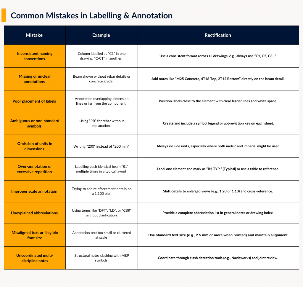
1. Suitable software: Selecting the right platform is the foundation for producing precise and coordinated structural drawings. While AutoCAD remains a staple for 2D drafting, Building Information Modeling (BIM) tools such as Revit and Tekla Structures have become industry standards for 3D modeling and documentation. These platforms allow for model-based drawing generation, real-time design updates, and clash detection, reducing errors, saving time, and improving coordination with architectural and MEP teams.2. Standard Symbols / Legends:Consistent labelling and annotation ensure that every structural element is correctly understood. Errors such as inconsistent naming, missing details, poor label placement, or ambiguous symbols can lead to confusion and costly delays.To maintain clarity:
Use a standardized symbol library and naming conventions.
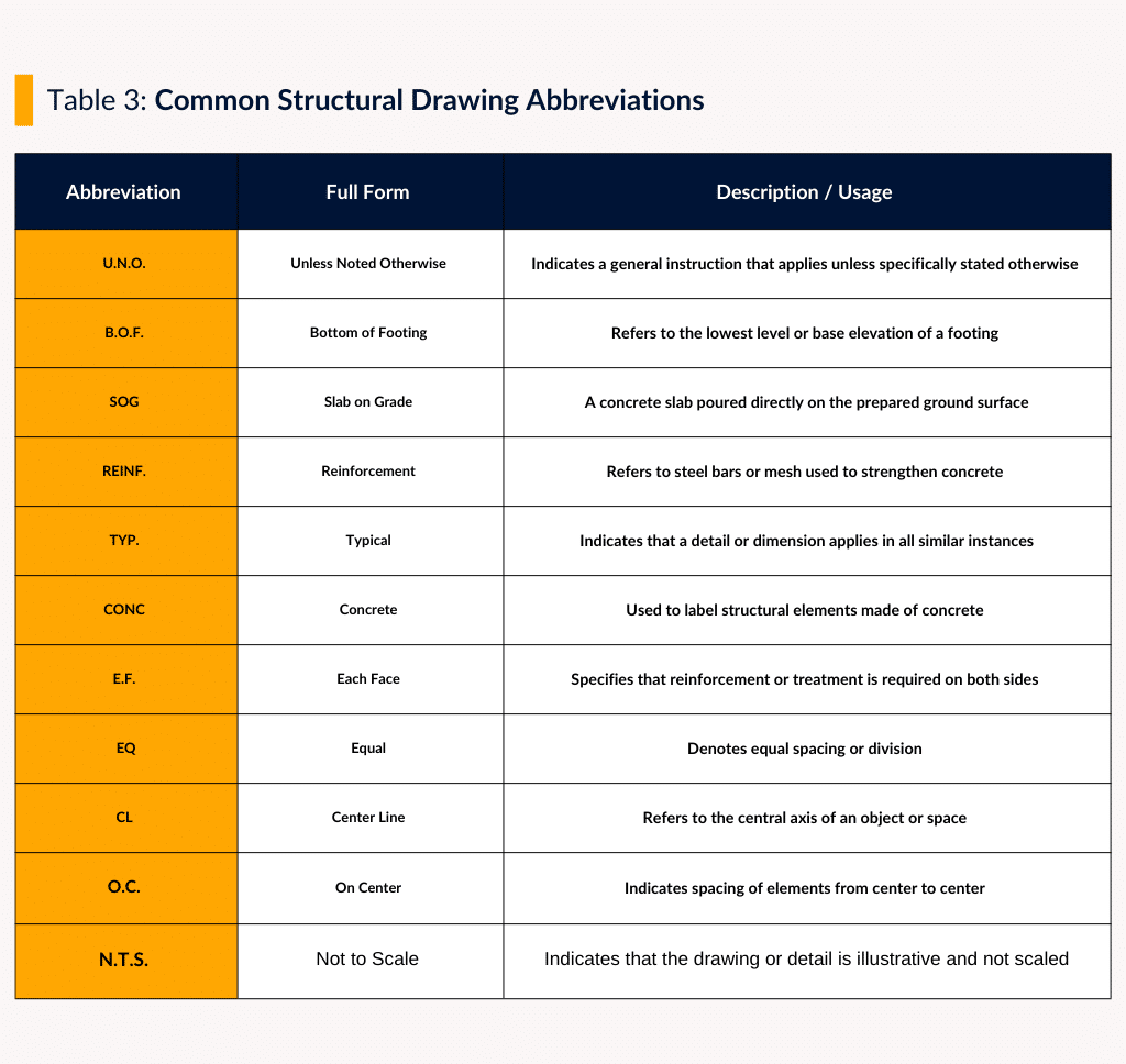
Include a legend and abbreviation list on every sheet.
Make sure annotations are legible, complete, and unit-specific.
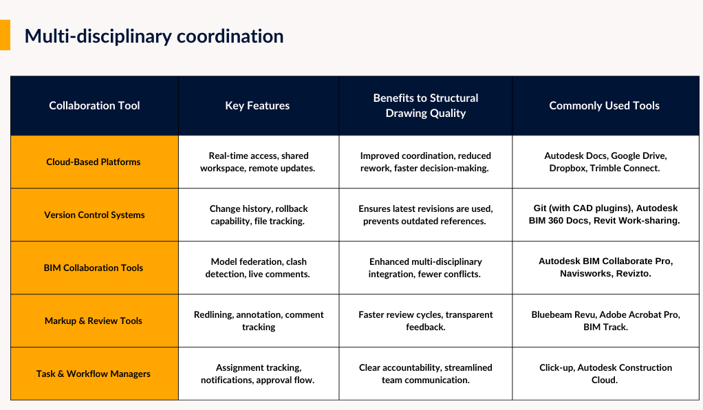
3. Multi-disciplinary coordination: Structural drawings are not created in isolation—they must integrate seamlessly with architectural, MEP, and other project drawings. Cloud platforms, version control systems, and BIM collaboration tools ensure every discipline works from the latest version.
Using the right platforms can help us make structural drawing sets that meet top quality and accuracy standards.
4. Code compliance:Drawings must meet local building codes and recognized industry standards. This includes:
Seismic and wind load design details
Identification of lateral force-resisting systems
Inspection and testing protocols
Code compliance not only ensures safety and legal approval, it also speeds up permit processes and avoids redesign delays.
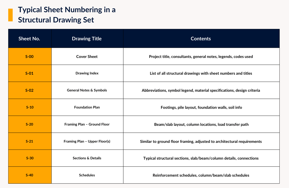
5. Drawing Organization and Presentation Standards:A clear and consistent presentation is essential for a high-quality structural drawing set. A well-organized package typically includes:
Cover sheet with project details, consultant information, general notes, legends, and applicable codes.
Drawing index for quick navigation.
Consistent sheet numbering to maintain order and improve coordination.
Uniform text styles, dimensions, line weights, and symbols create a visual language that is easy to follow, reducing misinterpretation between design and construction teams.General notes, design criteria, and abbreviation definitions should be clearly presented so both engineers and contractors can interpret the drawings without confusion.Revision control—using clouding, delta markers, and version history—ensures that all project phases use accurate, traceable documentation.6. Add sections and details for clarity:In structural drawings, clarity lives in the details. Sections and connection details should do more than satisfy code—they should anticipate how the structure will actually be built. Foundation sections must consider soil conditions, waterproofing, and tolerances, not just dimensions. Connection details for steel and concrete should specify type, size, and placement in a way that leaves no room for field improvisation. Reinforcement layouts should reflect realistic installation practices, with rebar sizes and spacing coordinated across drawings. The more complete and coordinated the details, the less likely a contractor will need to “figure it out” on site.
7. Precision and detailing:Precision is a core attribute of any high-quality structural drawing set. To ensure clarity and constructability, several key elements must be accurately incorporated:
Scale:Choosing the right scale is critical since it determines the level of detail a drawing can convey. Commonly used architectural scales include:
1:100 or 1/8" = 1'-0" for general layouts
1:50 or 1/4" = 1'-0" for more detailed plans
1:20 or 1:10 for sections and connection details
Always ensure that the scale is clearly indicated on each drawing sheet.
Grid systems that align across disciplines: Structural, architectural, and MEP grids must match perfectly; misalignment is a coordination time bomb.
Dimensions that build, not confuse: Dimension from fixed, logical reference points and avoid overloading drawings with redundant measurements.
Loading information where it matters: Show load values and reactions directly on relevant drawings so the data isn’t buried in a report.
Notation with discipline: Keep symbols, abbreviations, and labels consistent—small changes in notation can cause big mistakes in the field.
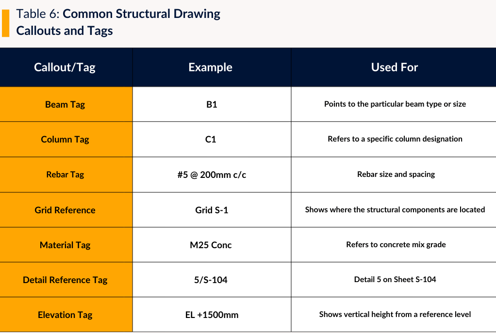
8. Callouts and Tags
Callouts and tags should function like a GPS—pointing directly and reliably to the right detail, section, or specification. Inconsistent or missing callouts force costly clarifications mid-project.Best practice: Audit callouts before issue—pick a few at random and confirm they lead to the correct, updated details.
9. Quality Assurance/Quality Control (QA/QC):
A robust QA/QC process ensures structural drawings are accurate, consistent, and code-compliant before they reach the site. This involves peer reviews, senior-level oversight, and coordination with architectural and MEP teams to detect errors, omissions, or discrepancies early.
Effective methods include:
Redline markups during internal reviews to flag unclear or incorrect details.
Layer-wise audits to ensure correct line types, colours, and standards.
Coordination checks using overlays or BIM clash detection to avoid conflicts.
Checklist-based verification of scale, grid references, reinforcement detailing, and load notations.
Revision control logs to track updates and maintain version history.
Cross-verification with structural analysis outputs to align detailing with calculations.
By applying structured, repeatable QA/QC procedures, every drawing can be validated, standardized, and aligned with project and regulatory requirements — preventing costly rework and ensuring smooth construction execution.High-quality structural drawings form the backbone of successful construction, ensuring seamless communication between designers, engineers, and builders.
At Intrivis, Inc., we go beyond delivering drawing sets, we deliver clarity, consistency, and confidence. Our experienced team produces accurate, constructible, and code-compliant drawings that guide your project from concept to completion. With our reliable modelling and drafting expertise, you can focus on creating great architecture while we ensure the technical precision behind it. Let’s bring excellence to your next project — reach out to discuss how we can support your structural documentation needs.


 Using the right platforms can help us make structural drawing sets that meet top quality and accuracy standards.
4. Code compliance:
Drawings must meet local building codes and recognized industry standards. This includes:
Using the right platforms can help us make structural drawing sets that meet top quality and accuracy standards.
4. Code compliance:
Drawings must meet local building codes and recognized industry standards. This includes:
 General notes, design criteria, and abbreviation definitions should be clearly presented so both engineers and contractors can interpret the drawings without confusion.
Revision control—using clouding, delta markers, and version history—ensures that all project phases use accurate, traceable documentation.
General notes, design criteria, and abbreviation definitions should be clearly presented so both engineers and contractors can interpret the drawings without confusion.
Revision control—using clouding, delta markers, and version history—ensures that all project phases use accurate, traceable documentation.
 9. Quality Assurance/Quality Control (QA/QC):

